This is my digital portfolio. It includes a collection of projects that I worked on throughout my
schooling at UF and outside the classroom with the design team I joined. I have added images that I have
available.
Website Layout
3D Printed Arm Final Assembly
CAD Rendering for 3D Printed Arm
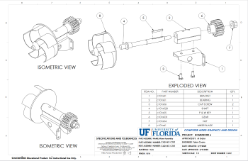
Full Assembly BOM for 3D Printed Arm
Weil Hall Clock Tower
SDC Robot
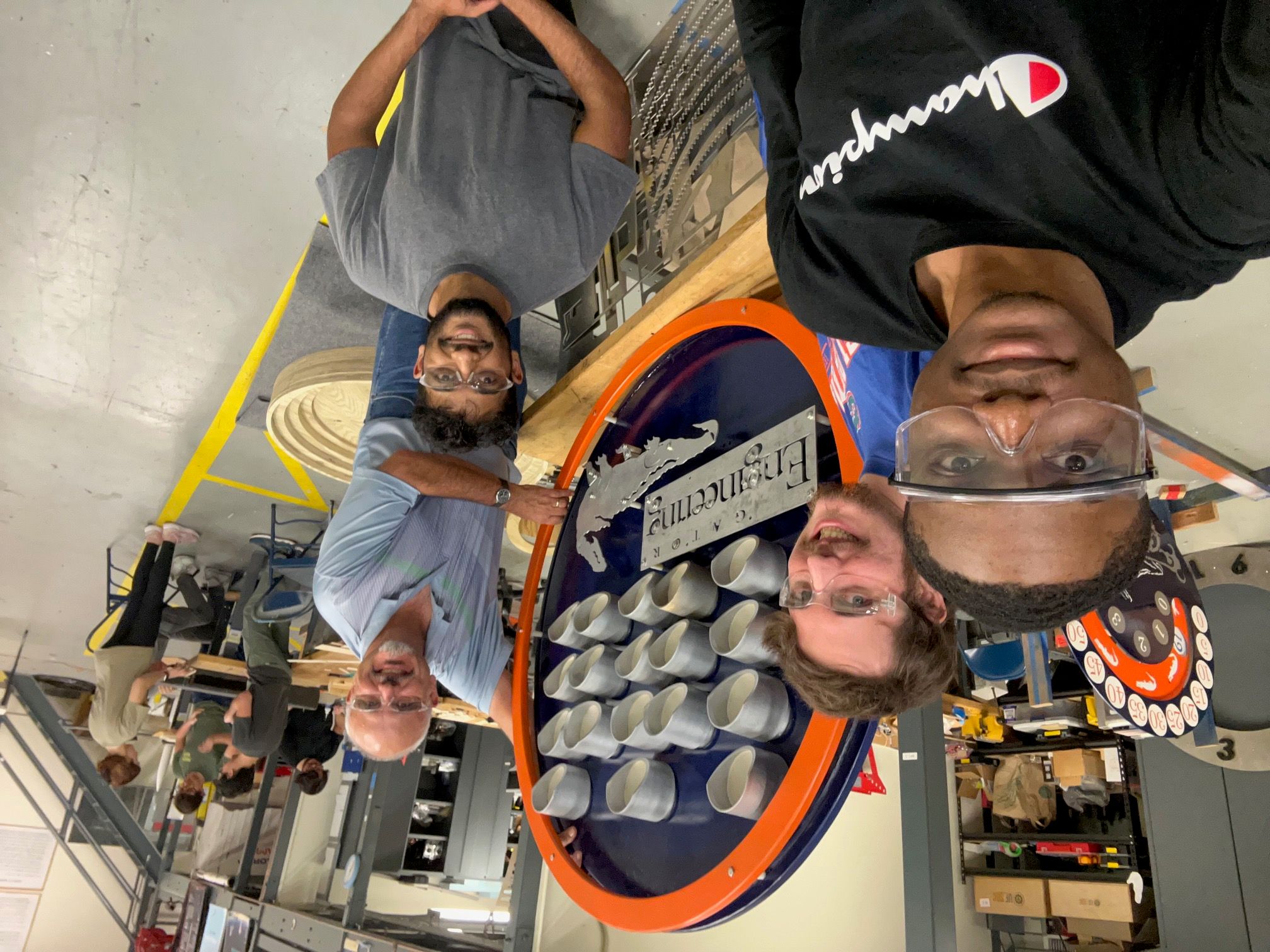
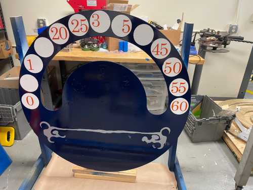
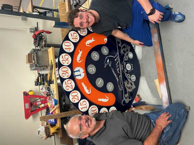
Picture with Dr. Griffis, Monzurul, Emmanuel, and I and the Wandering Dial
Clock
Photo with Dr. Griffis, Emmanuel, and I and the Wandering Dial Clock
Manufacturing Consulting at Hagen & Company Inc., Jan-8 2024 - Nov-8 2024
Description
I worked as a consultant for the continuous improvement of manufacturing processes. In this role I
traveled to manufacturing plants and lead a team of plant personnel to improve the efficiency of the
plant. I worked here for 10 months until I was let go because I was not developing quickly enough for
the social aspects of the job. There are many salesman aspects of a consulting position and I don't like
talking, so this position was not a great fit.
Actions
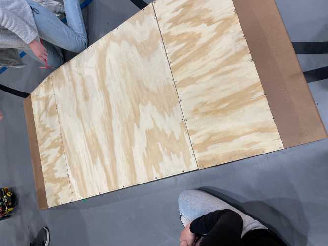
While I was employed, Hagen was primarily working with a wood products business. I worked with a couple
of different plywood manufacturing plants, although it was mainly with one. I completed studies to
identify and prioritize the actions to increase the performance of the line. I also worked with the team
to involve them in the studies and results to effectively drive actions to improve the performance.
Results
Through my work with the team I was able to improve the efficiency of the bottleneck of the mill by
22.1%. Most of this return was obtained through increasing the speed of the main bottleneck by 32.6%. I
worked with the team on many mechanical and PLC improvements to increase the speed this much. For
example, cycle time analysis on the lathe lead to reducing block cycle time by 0.4 seconds for every
block through some optimizations with the PLC logic and tuning set points.
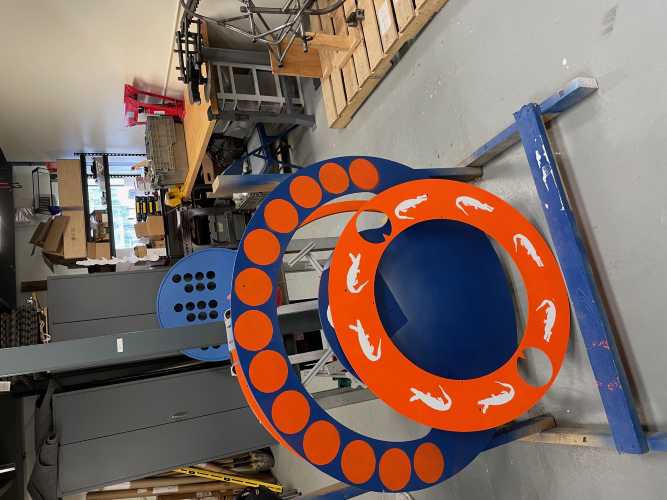
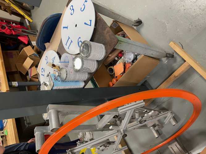
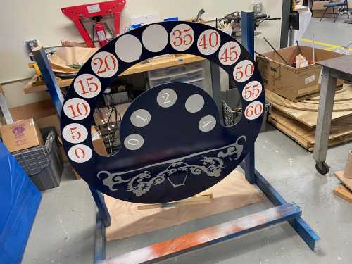
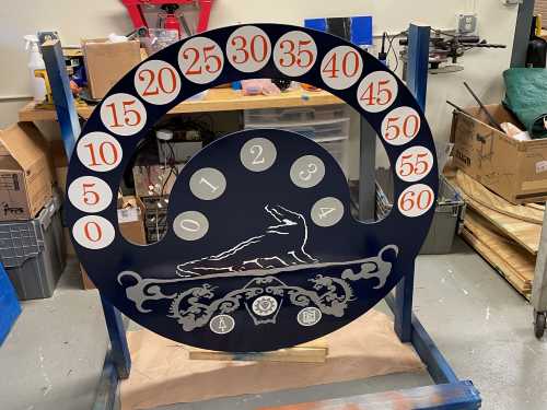
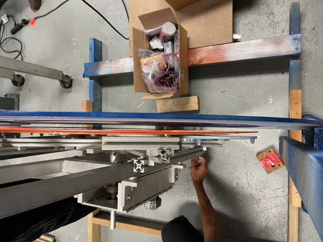
The Weil Hall clock tower, one of the clock towers on the campus of UF only had 2 working faces and they
needed repair. SDC was tasked with repairing the 2 faces and designing/building 2 more faces to replace
the plywood that had been there for decades. One of them was a binary clock that showed the time through
lights turning on across a couple of columns and the other was closer to a typical watch design.
Action
Throughout my time in SDC I worked from being a team member to the vice president and finally president
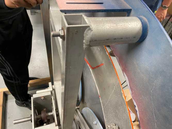
of the design team. Following this, my role changed as I was working on the clocks. Initially, I worked
with designing one of the new faces for the clock. Once we had uninstalled the clocks, I focussed on
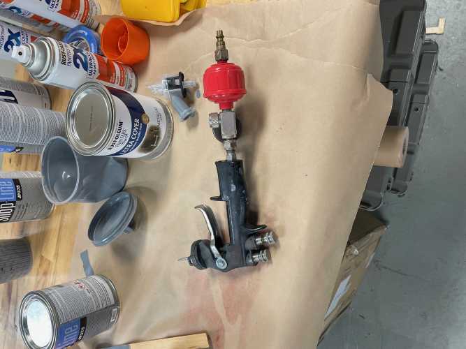
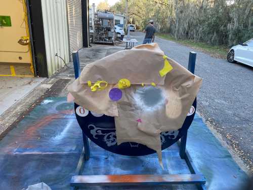
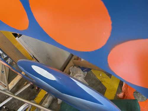
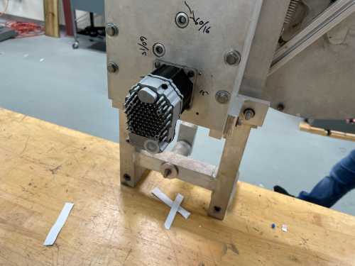
refurbishing them. I sanded them, both metal and wood, primed and painted them. I also dissasembled and
changed the motor of the watch clock with the help of our advisor, Dr. Griffis. With my role expanding,
I organized meetings and taught other team members more on what I had learned.
Results
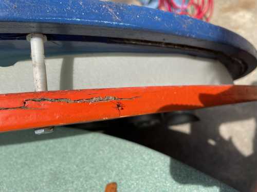
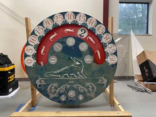
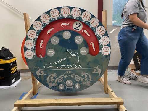
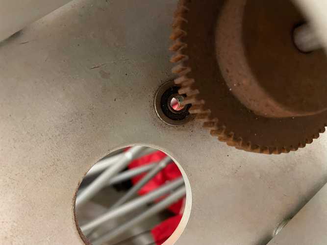
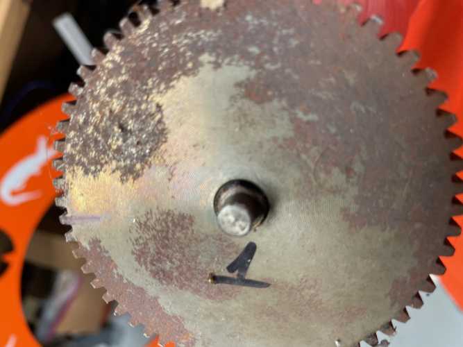
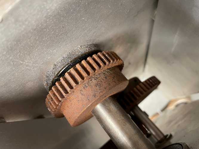
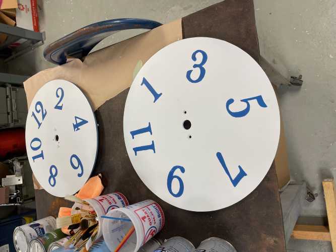
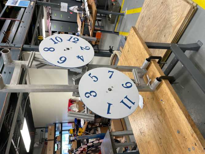
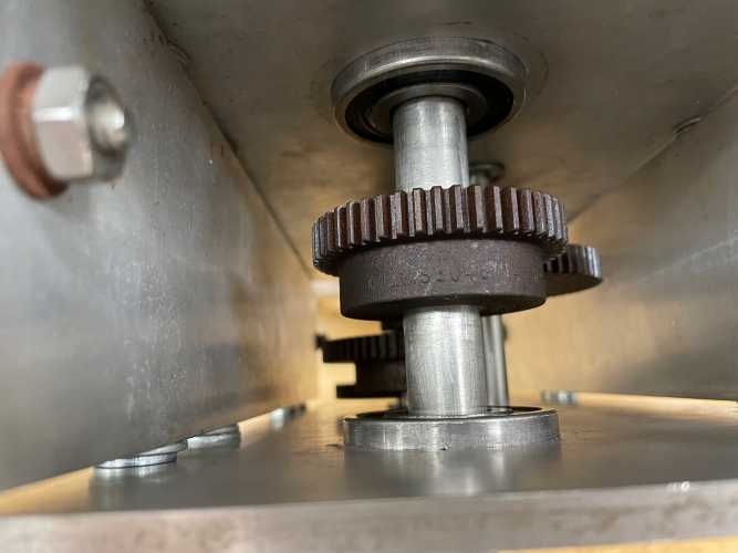
I learned some skills while refurbishing the clocks. We did not understand how the clocks worked, so we
needed to reverse engineer the clocks to understand them. I kept good track of where everything went and
was able to piece together how the watch clock turned to tell the time. This process did not go smoothly
as there was lots of trouble getting the gears to turn. I applied knowledge of gear relations to check
tolerances, understand the speed of the motor to accurately tell the time and troubleshoot. It ended up
being a lubrication issue that would bind the gears, so I also cut and bent sheet metal to enclose the
gearbox for a lubrication system.
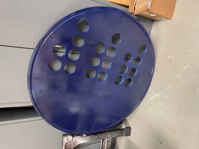
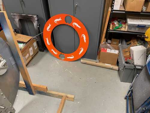
Binary Clock
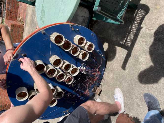
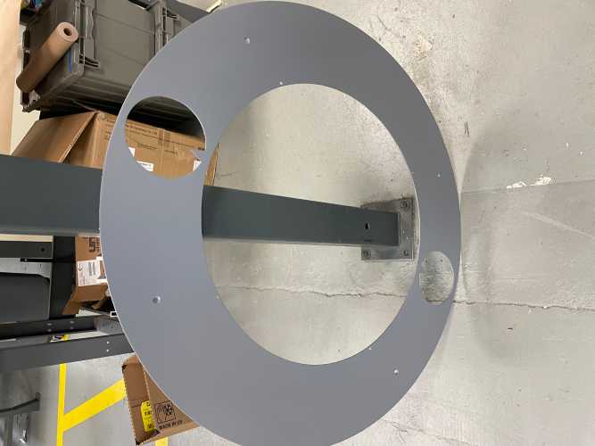
First Removal of the Clock
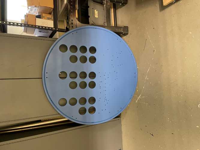
Dissasembled Back Face
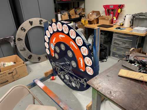
Rings of the Binary Clock
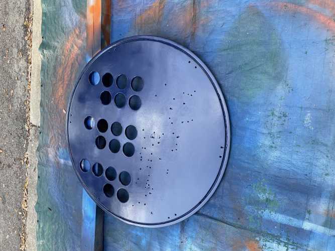
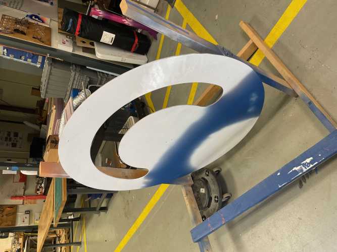
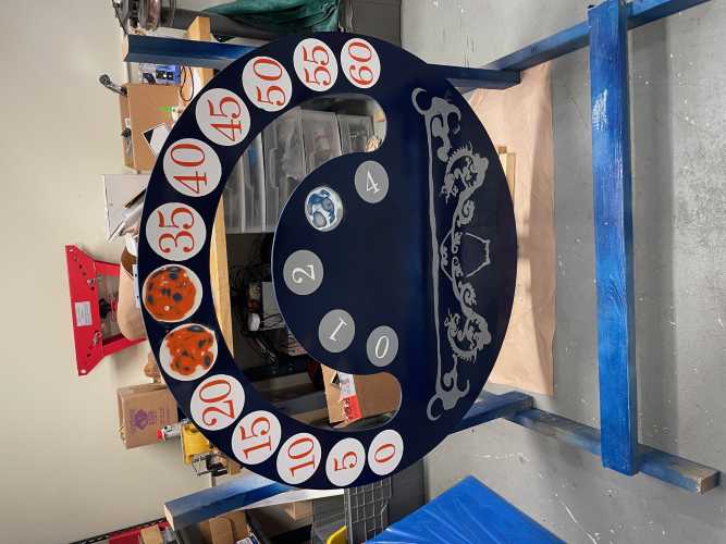
Freshly Painted Back Face
Freshly Painted Back Face
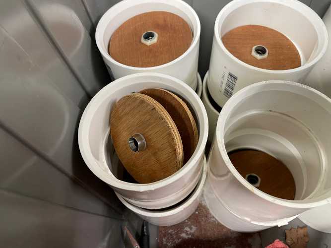
Internals of the Lights
Casings of the Lights
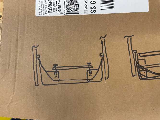
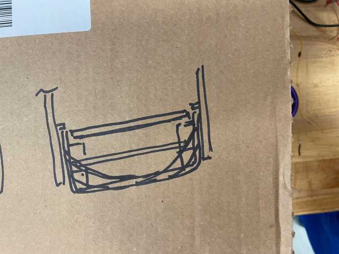
Design for new Light Cover
Design for new Light Cover
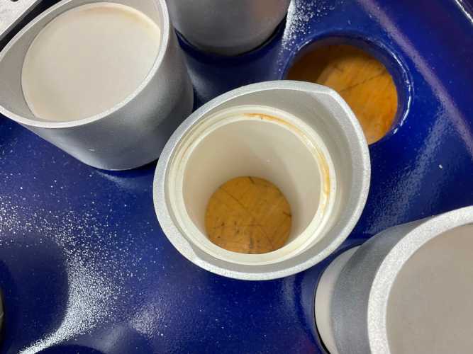
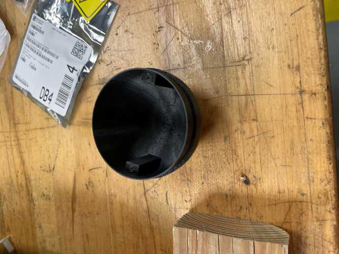
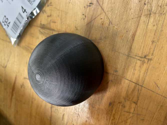
3D Print of the New Light Cover
3D Print of the New Light Cover
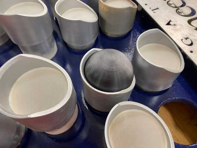
Test Fit of the new Light Cover
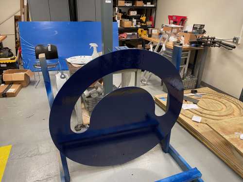
Reassembly After Painting
Picture with Dr. Griffis, Monzurul, Emmanuel, and I
Picture with Dr. Griffis, Monzurul, Emmanuel, and I
SDC was originally created as a design team under the UF ASME chapter to compete in the ASME Student
Design Competition with a very original name. Following the Covid-19 epidemic, compeitions were not
being held in person until this year. This is why I got a start working on the clocks and then worked
with this competition. The goal of this years competition was to design and build a robot to move
weights across an arena only being powered by solar and wind energy. The competition guidelines are
here: ASME SDC 2023.
Action
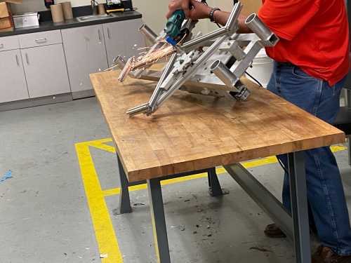
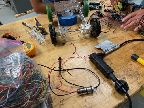
Initial Prototype Construction
Final Prototype
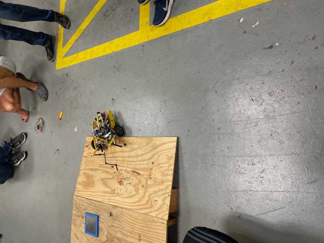
Final Prototype on Ramp
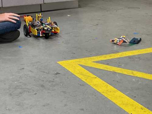
Robot on the Ground
Competition Ramp
I was vice president at this time, so I wanted to fill in where help was needed and not overshadow the
team doing the designing. During this time I was also working on the clocks, so I mostly helped with the
fabrication of the robot. I soldered many of the elctronics and got the prototype functional.
Results
Robot at the Competition
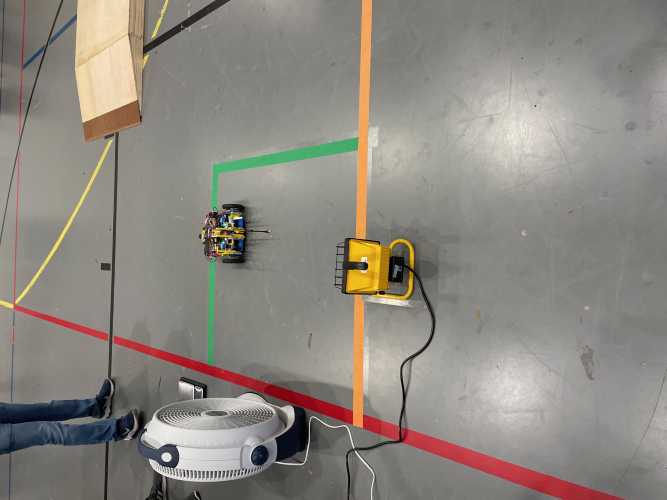
We were unable to get the solar panels to charge our capacitors very quickly, so I had a different
idea.
We were provided a single AAA battery to use to open any charging mechanisms we may have and I thought
it would be possible to create a robot to run entirely on that battery. 2 weeks before the competition,
we scraped our design and rebuilt it with Legos and small DC motors to run on the single battery. In the
first round we placed 4th seed out of 14 and then were knocked out by the 5th seed in the brackets. They
had some technical difficulties in the first round and were much stronger in the bracket.
Prosthetic Arm - Mechanical Design 3, Fall 2023
Goal
Full Assembly BOM
The goal of this project was to create a low-cost prosthetic arm. To achieve this, my group chose to
create an almost entirely 3D printed arm with OEM pins, motors, and fastenings. This was a seven person
group project and I primarily spent time with the CAD, 3D prints, and wiring.
Action
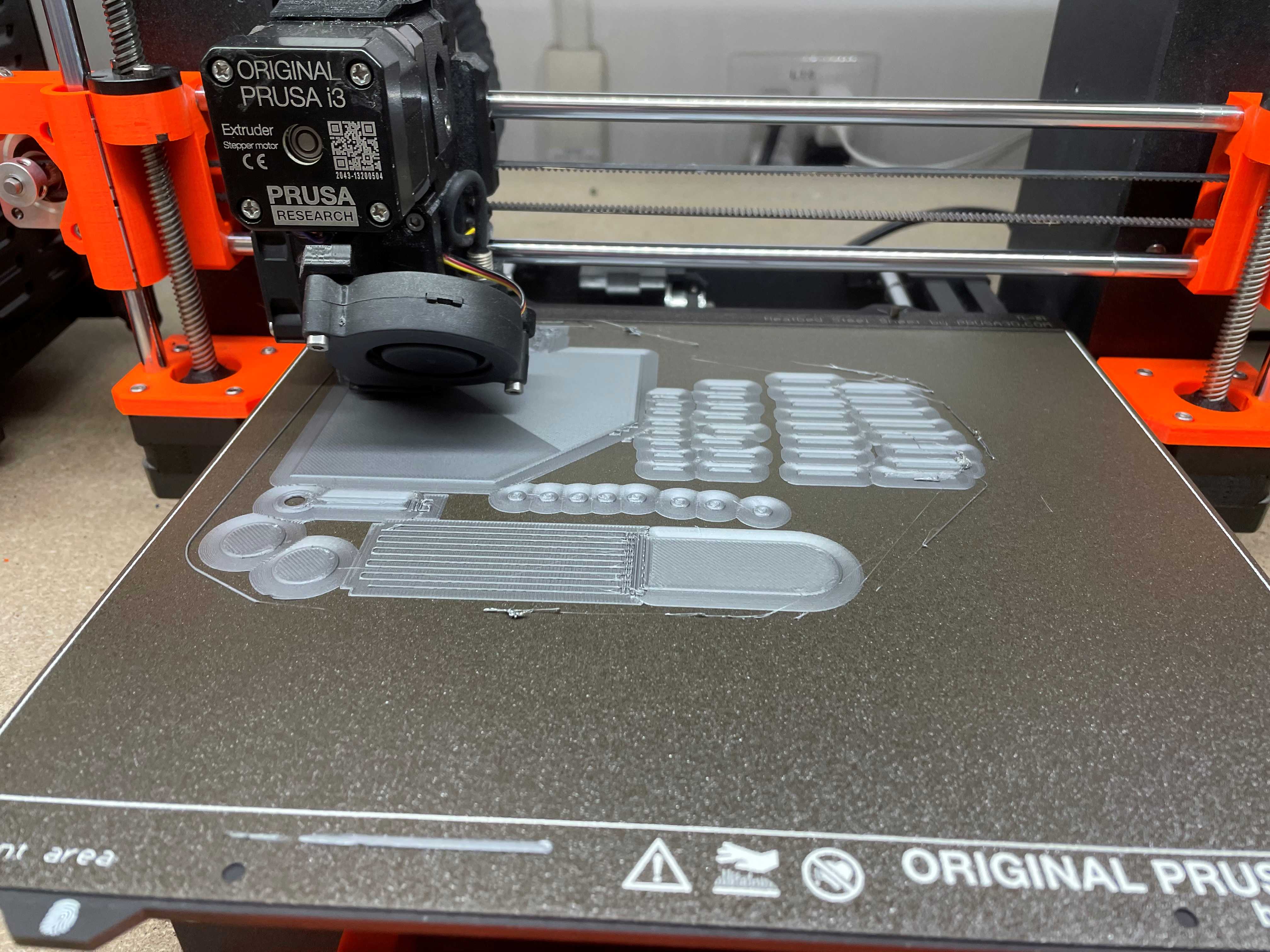
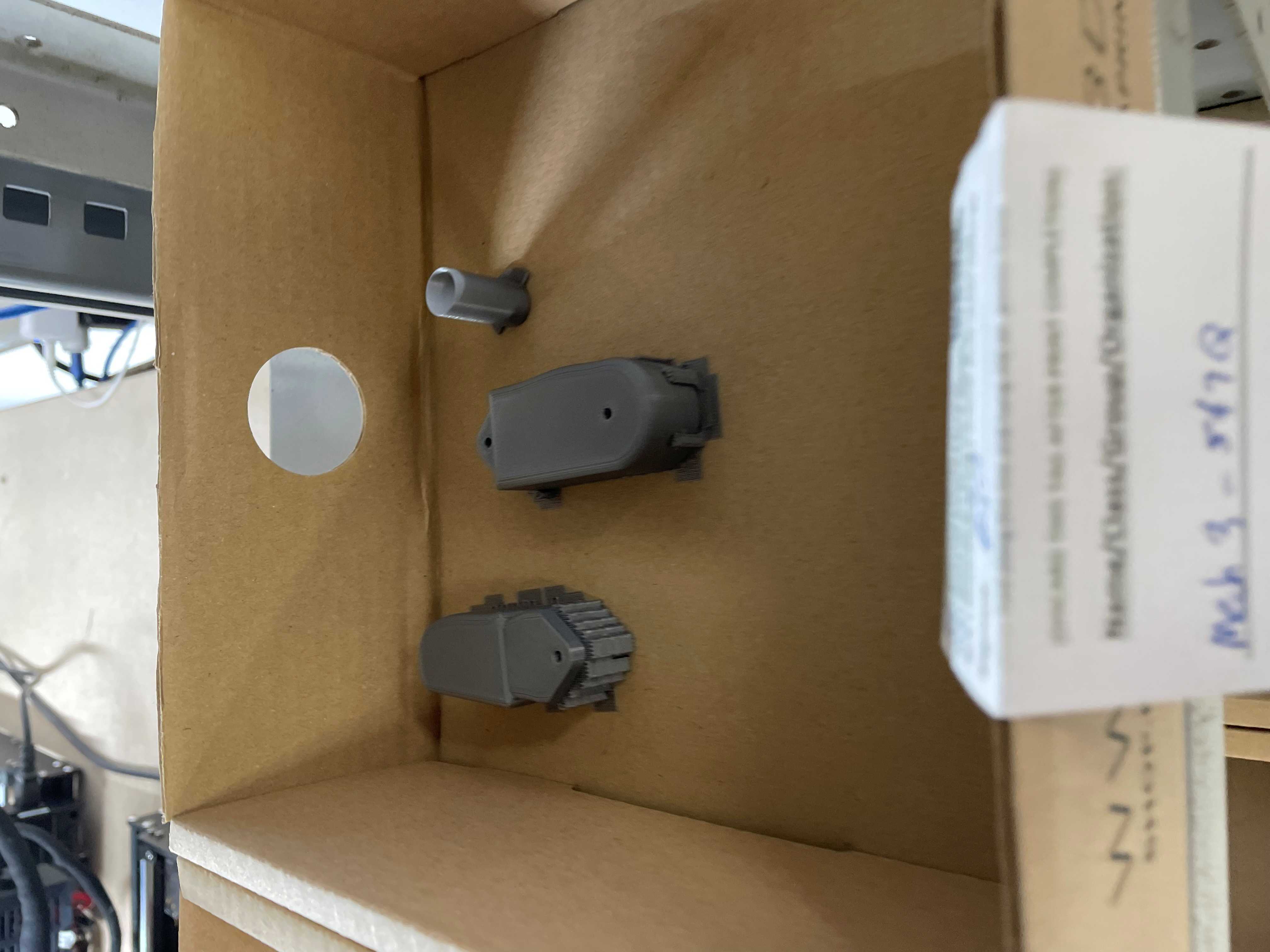
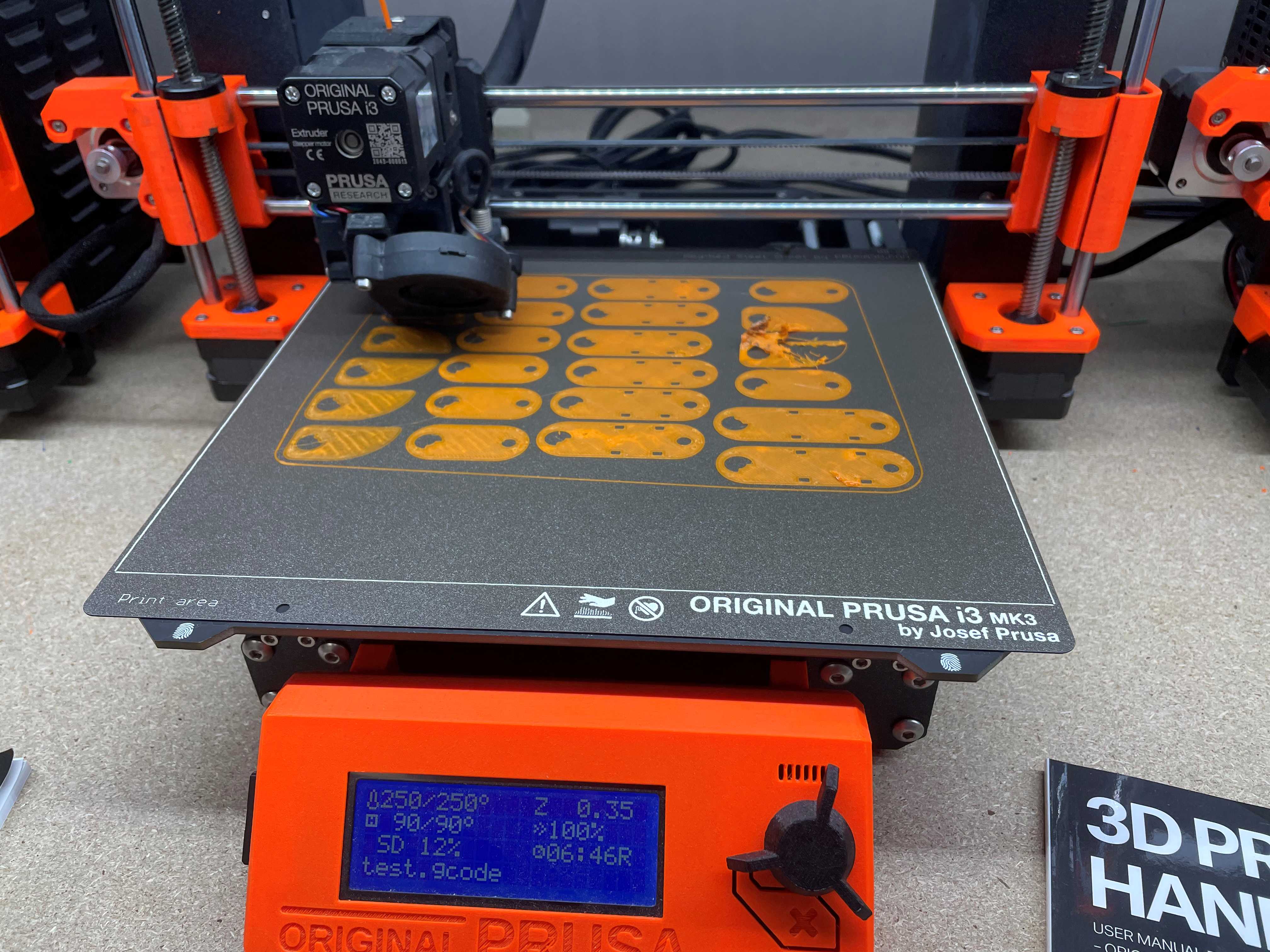
Prusa MK3 Printing
3D Prints
Printing out the Finger Parts
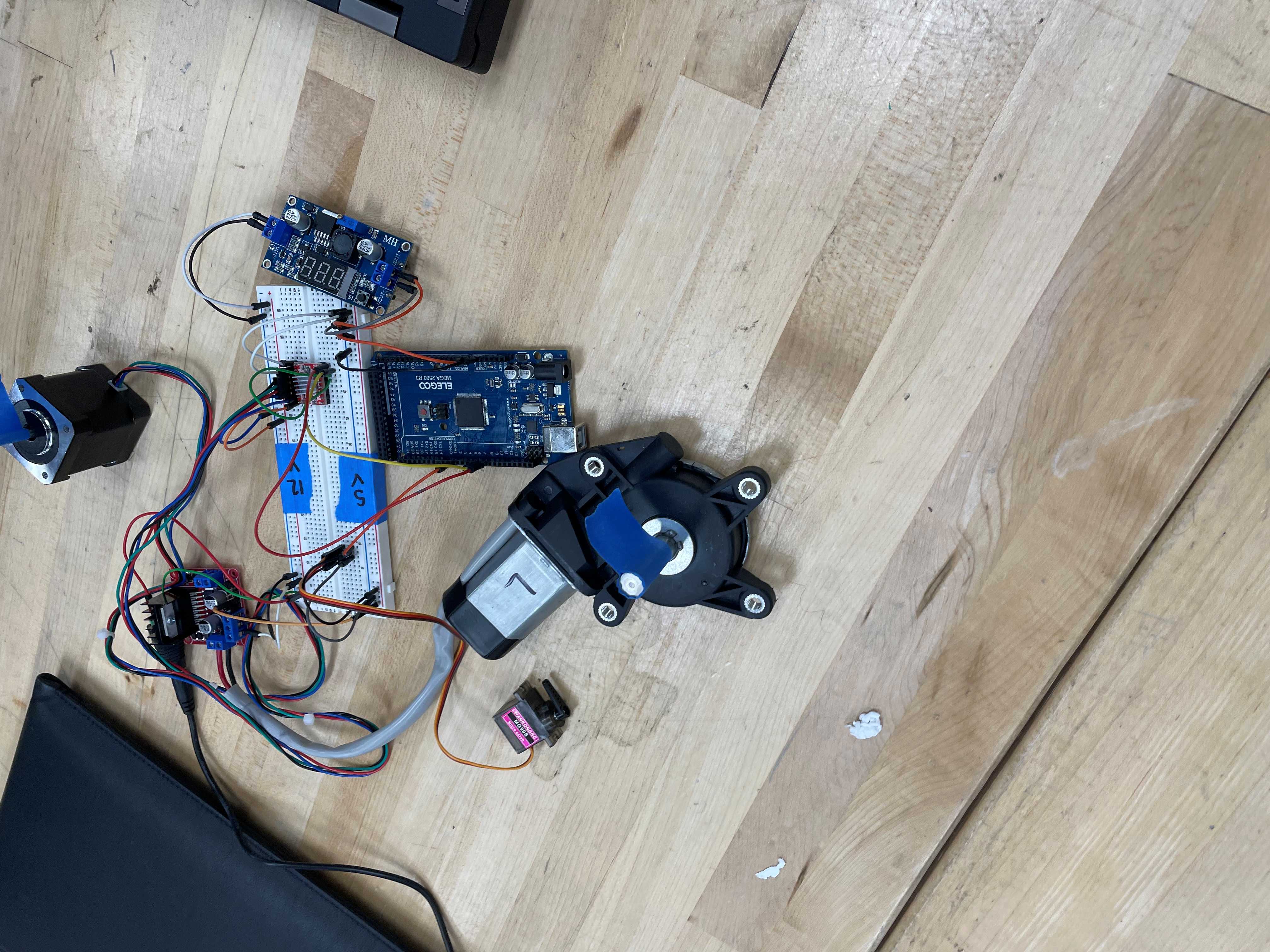
Arduino setup for the Electronics
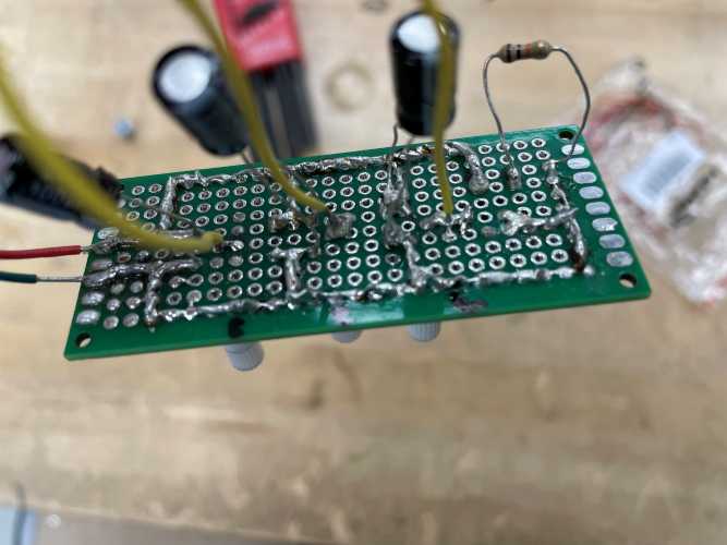
Bottom of the board Soldered
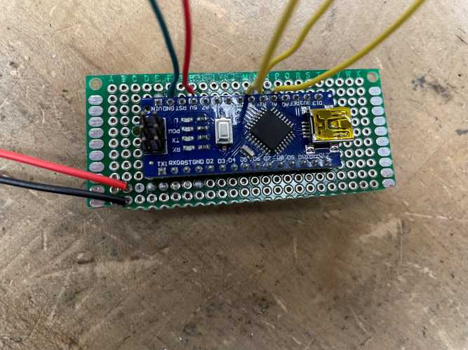
Arduino Uno Soldered to the Board
Wires and Capacitors Soldered to the Board
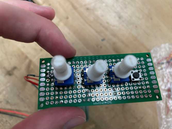
Potentiometers Soldered to the Board
The lab had Prusa MK3 printers, so I imported the STL files from SolidWorks to the Prusa G-code Viewer to
print them with the settings the lab prefered. I also cleaned up the prints and performed test fits to
update the CAD and makes sure the updates were syned to SolidWorks PDM. Once we had ordered parts and
after another team member had created the circuit board, I ensured everything was soldered together to
be functional.
Results
Final Prototype Assembly
Final Assembly Render
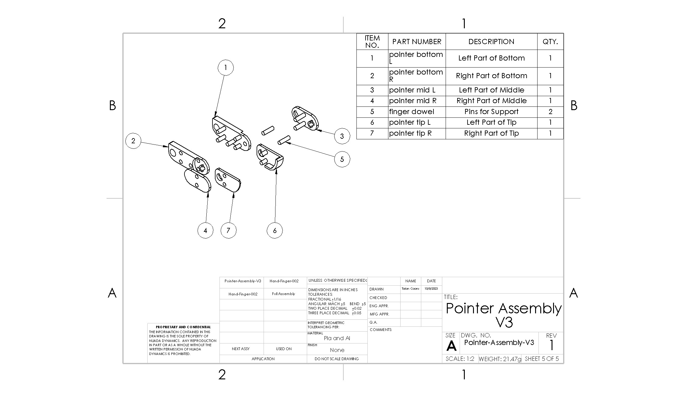
Finger Subassembly BOM
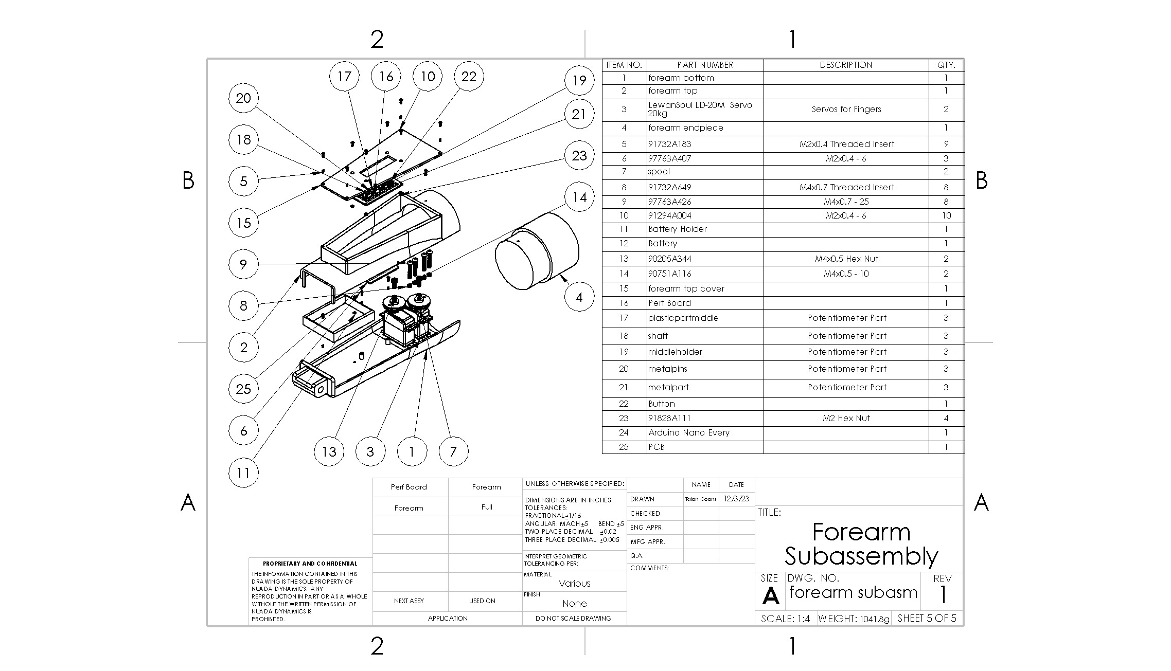
Forearm Subassembly BOM
Full Arm Assembly BOM
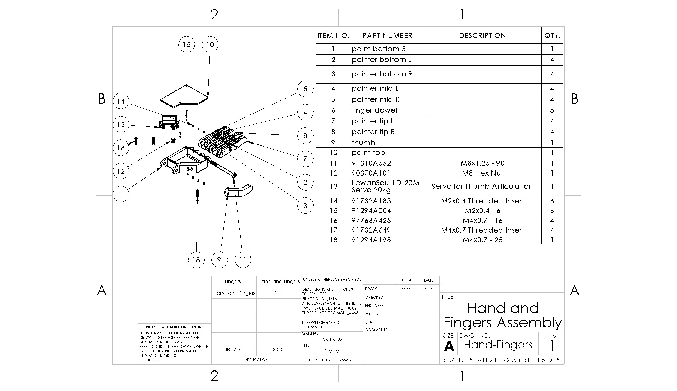
Hand Subassembly BOM
I worked in this group to create a working prototype. I also created many of the assembly drawings,
including the BOMs shown above. The link to the project is here: MAE
Website
Airfoil Drag - Aerospace Sciences Lab and Design, Spring 2023
Problem
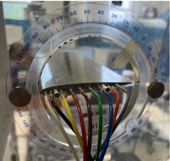
Sideview of the airfoil with pressure ports attached
The final project for this lab was to investigate a phenomena further using the skills we developed
through the semester working the the lab's open circuit eiffel wind tunnel. I worked in a group of 3 to
test the affect on stall conditions of adding roughness strips to the top of an airfoil. We chose to
base our investigation around this Virginia Tech
paper with some adjustments for our set up.
Methodology
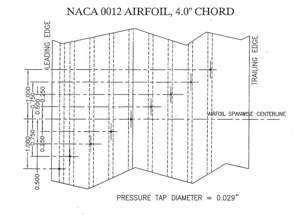
Spanwise Port Locations
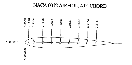
Streamwise Port Locations
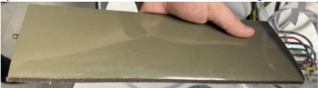
Sandpaper Attached to the Airfoil
I worked on the background research with adapting this trial to our lab and collecting data. We used a
symmetric airfoil with pressure ports on the top side of the airfoil to obtain the pressure gradient and
calculate the coefficient of lift. We needed to measure positive and negative angles of attack to obtain
the top and bottom pressures for the integration. They also needed to be smaller than the other paper
since the front-most pressure port was closer to the front of the airfoil.
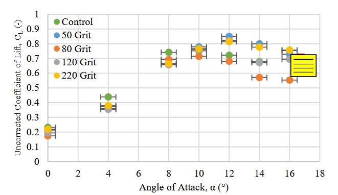
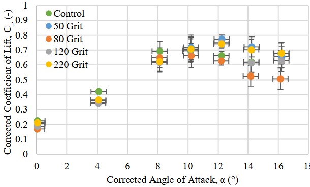
Results
Results Plot Before Boundary Corrections
Results Plot After Corrections
Unfortunately we did not see as much of a differentiation between the roughness strips as we had
envisioned. This was possibly due to extra silicon leaking out from the edges and adding roughness. We
also had the same profile for the negative angles of attack with a clear airfoil and possibly should
have added roughness strips to test if they impacted the other side even if they theoretically should
not have.
Cube Satelite - Aerospace Design 1, Fall 2022
Goal
Group Logo
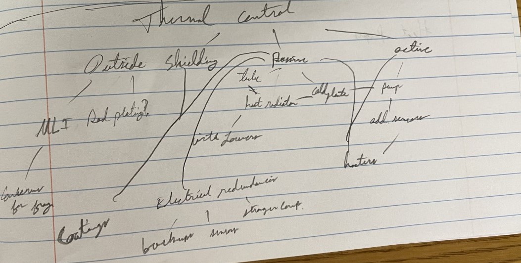
Inital Notes on Thermal Controls
The goal of this project was to create a CubeSat with a max size of 12U to survey potential landing spots
on the North pole of the moon with a 0.5 meter resolution than we currently have. This would be for a
theoretical LEWIS CubeSat Project to aid NASA's Artemis missions. In a team of 9, I was tasked with
determining the environmental controls for the CubeSat.
Actions
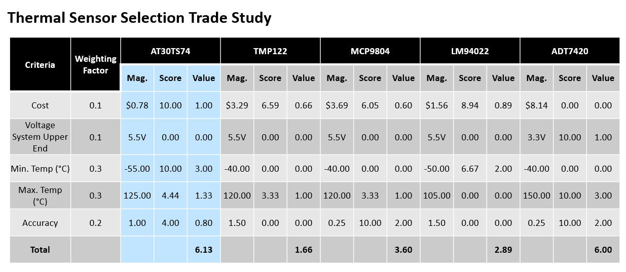
Thermal Sensor Trade Studies
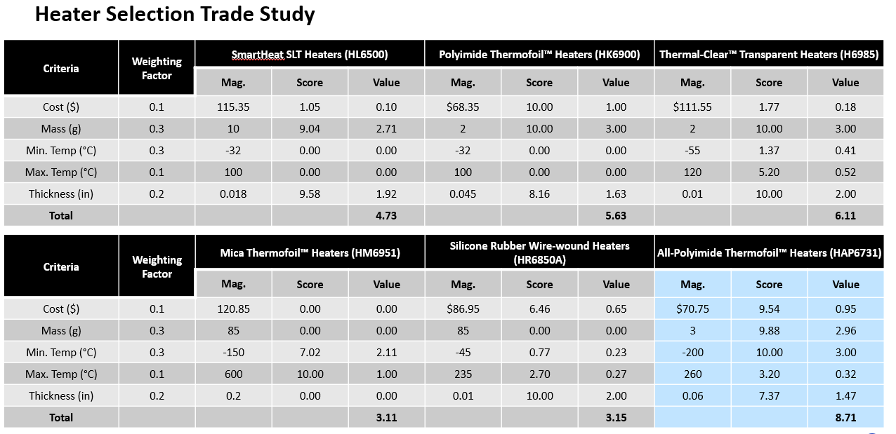
Heater Trade Studies
I found very little was necessary to survive the thermal
conditions, except the temperatures would be too low for the camera we had chosen. For added redundancy,
I determined using an active heating and passive cooling system would be sufficient for our satelite.
I completed trade stuides to determine the most effective components.
Results
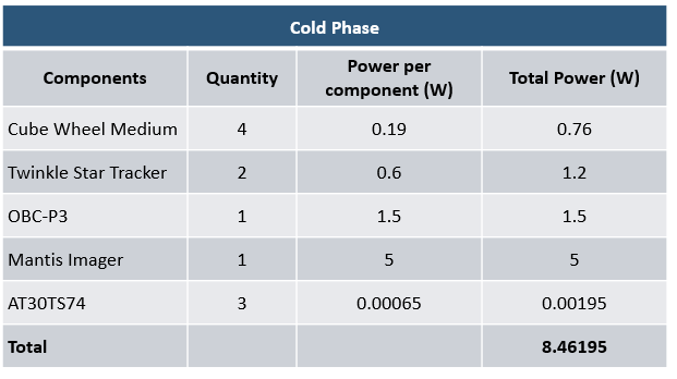
Component Load Cold Orbit
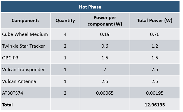
Component Load Hot Orbit
I worked with all the members of the group to determine the requirements for every subsystem of the
CubeSat and determined an active heating, passive cooling system to be sufficent for all the components.
The link to the project on the UF MAE website is here: Project Selene
Mechanical Design 1, Spring 2022
Problem
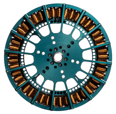
Motor Used as Generator
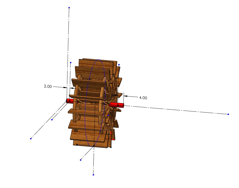
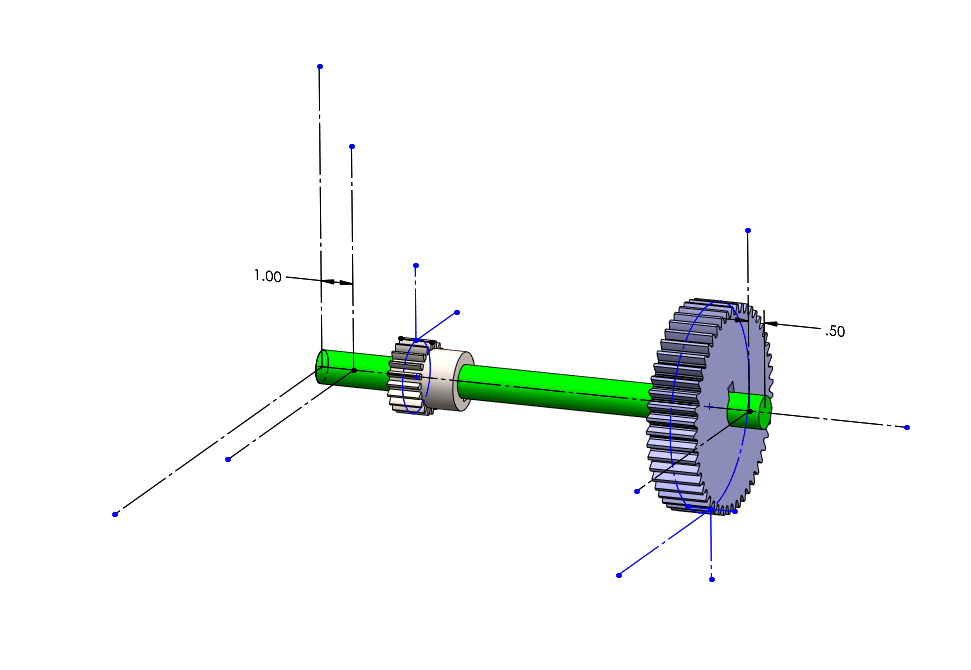
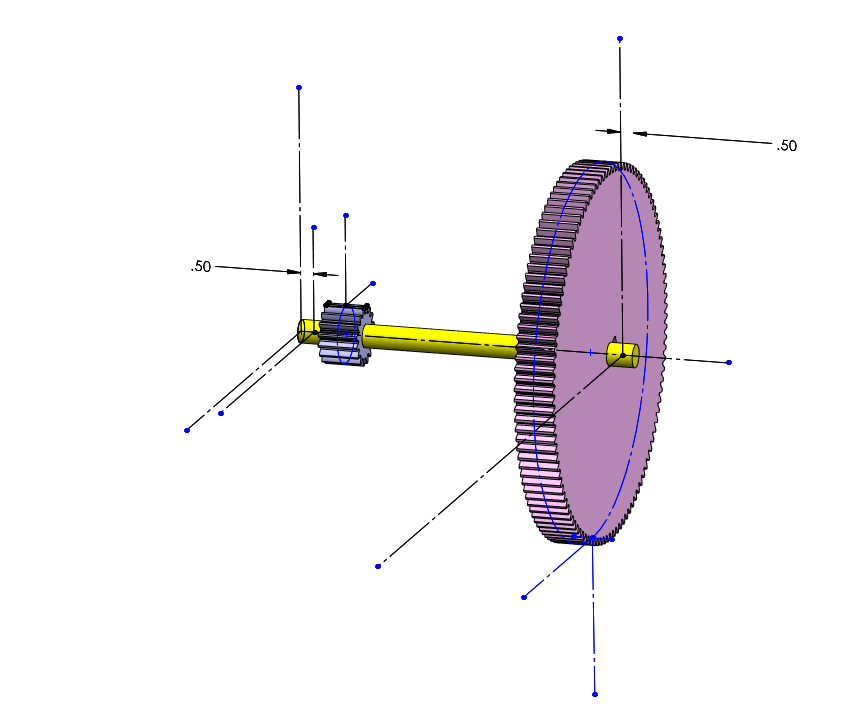
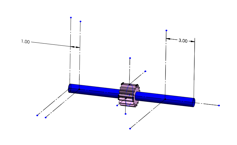
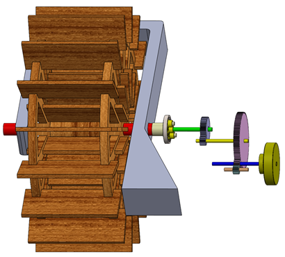
The final project of this course was to apply some of the principles we learned about gear trains and
include a bevel/planetary/compound reverted gear train to the system. I was in a group of 3 and we chose
to design the gear train to convert the motion of a waterwheel to power a home. We also used a planetary
to get extra speed from the waterwheel.
Actions
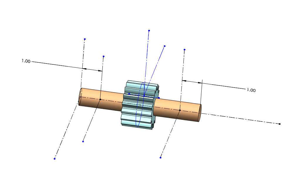
Shaft FBD
Planetary Shaft FBD
Another Spur Gear Pair Shaft FBD
Motor Shaft FBD
Idler Shaft FBD
We sized a 40kW motor to use as a generator and worked backwords with a constant flowing river to
determine the gear train. I worked with some of the calculations to determine bearings for evey shaft
and found actual bearings that could be used. This involved creating free-body-diagrams of every gear
shaft to determine the support reactions and appropriately size the bearings.
Results
Final Assembly
I applied my knowledge of gear trains to determine a train to turn a generator to power a house. The
motor used to model the generator was similar to the one pictured above. The gear train transferred
power from a waterwheel to generate the max power load of a typical house using a few pairs of spur
gears and a planetary gear.
Computer Aided Graphics and Design, Spring 2020
Problem
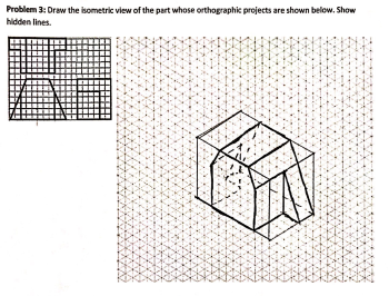
CAD Sketch Homework
Even with prior experience in CAD, taking this class was a requirement for the major. We used SolidWorks
for this class and also learned some GD&T basics.
Action
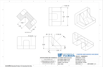
Mid-Class CAD Homework
Throughout the class I completed projects from the basic hand sketching to more complicated assemblies
and different drawing views. Using the parts and assemblies, I would create drawing files like the one
above.
Benefit
End of the Class Homework
I got to refresh my CAD skills before using them in future classes. The last homework
assignment had a more complicated assembly with an exlpoded view and BOM.
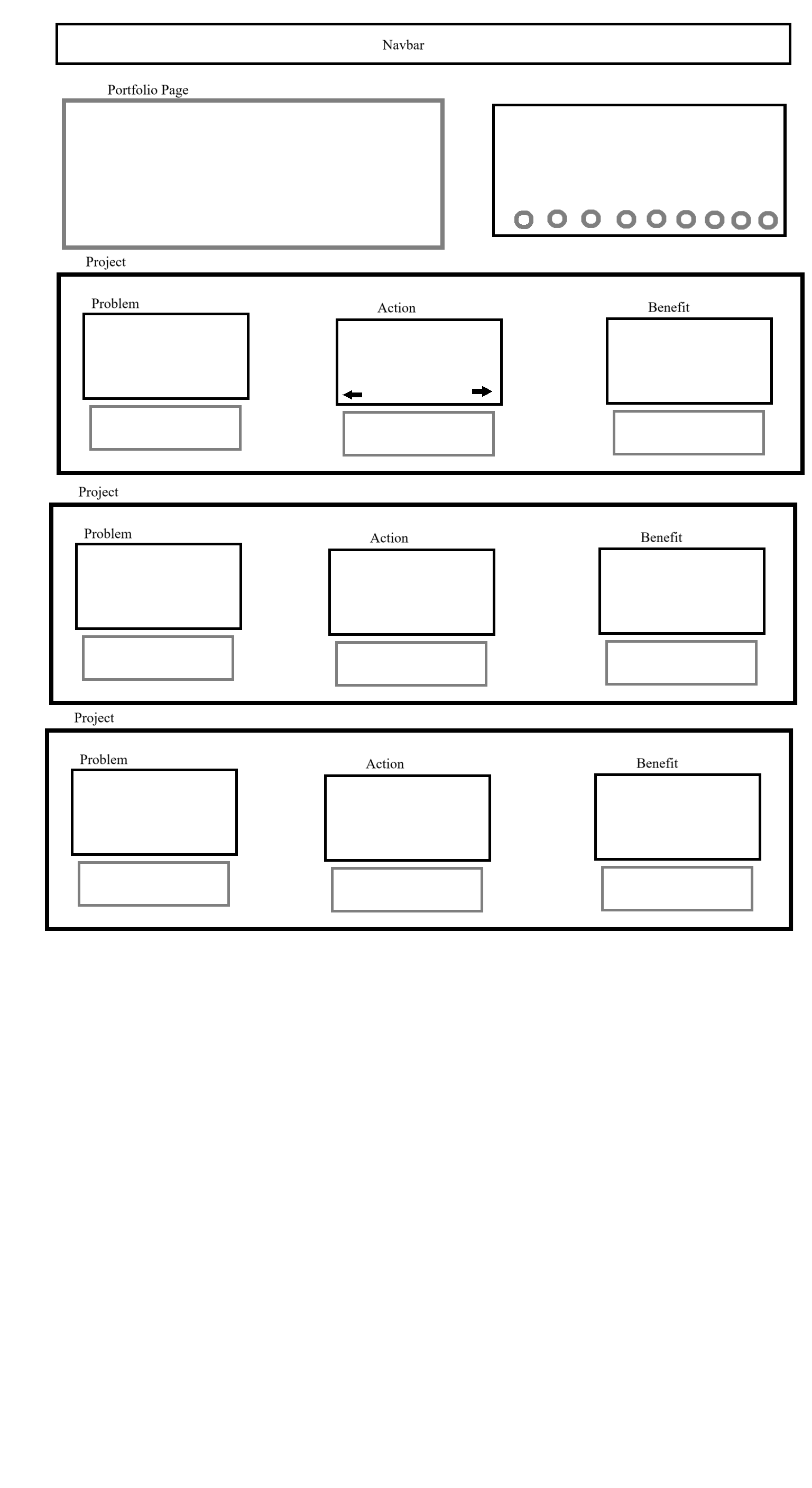 Website Layout
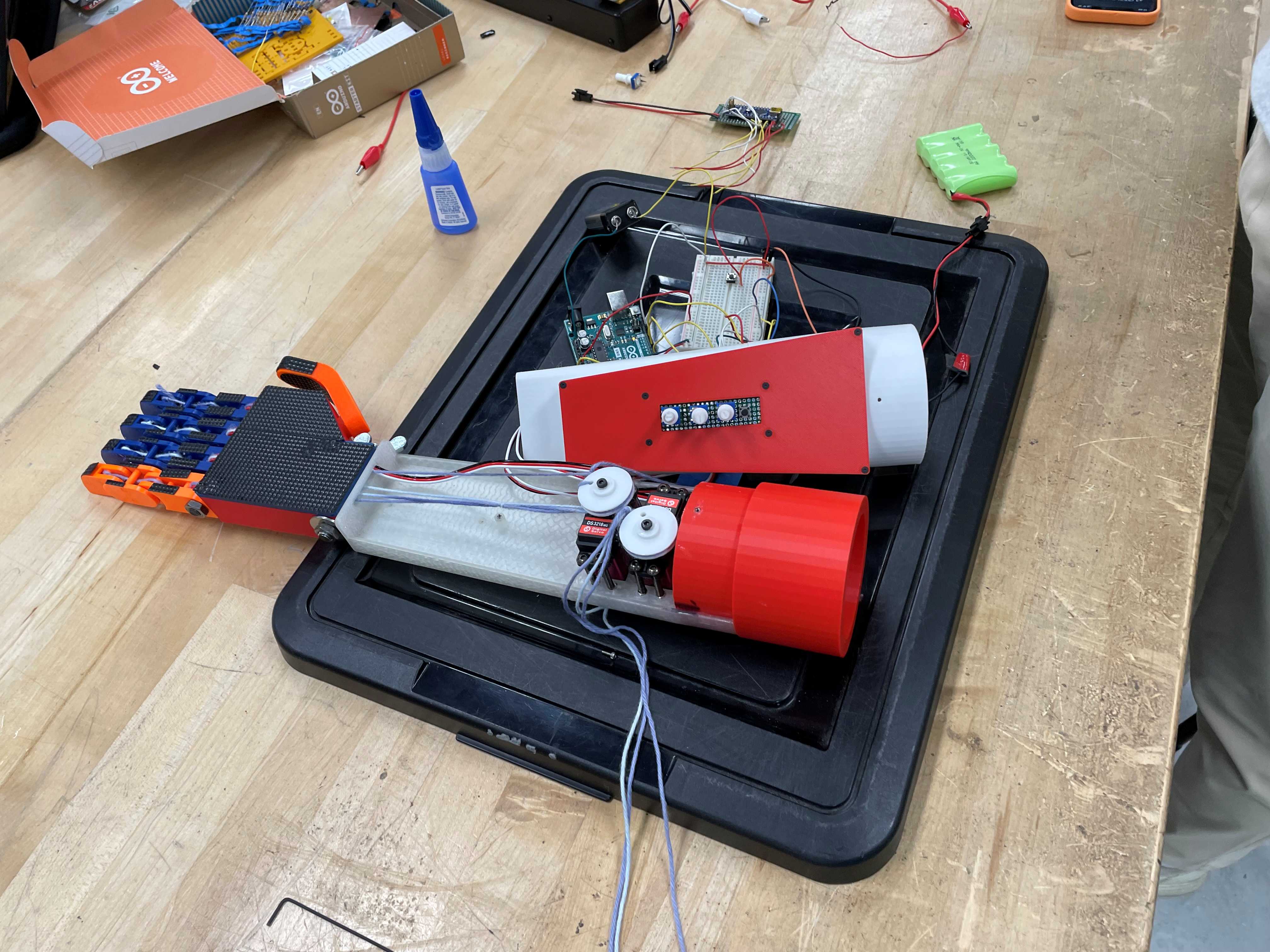 3D Printed Arm Final Assembly
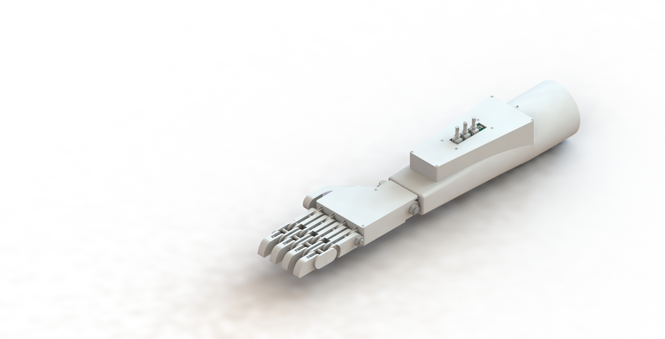 CAD Rendering for 3D Printed Arm
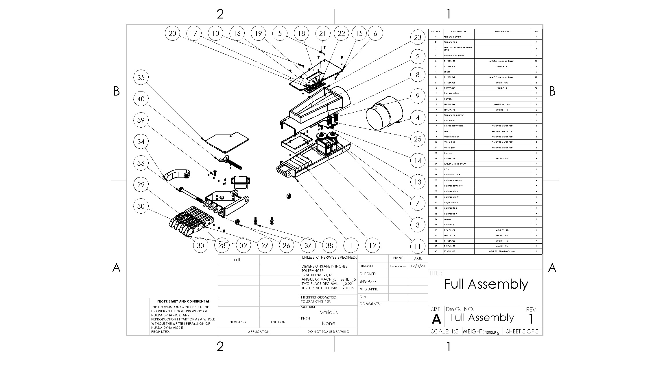 Full Assembly BOM for 3D Printed Arm
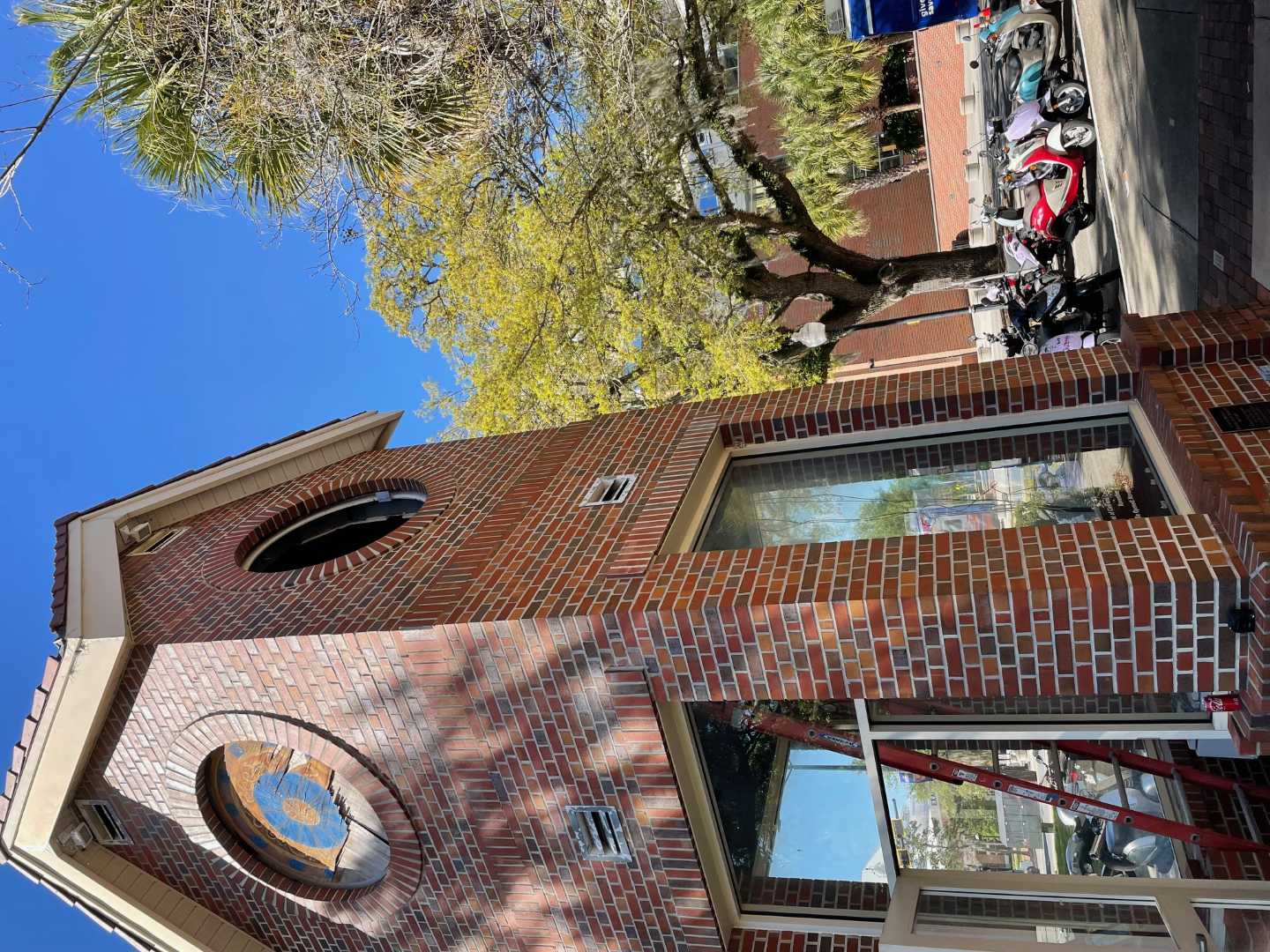 Weil Hall Clock Tower
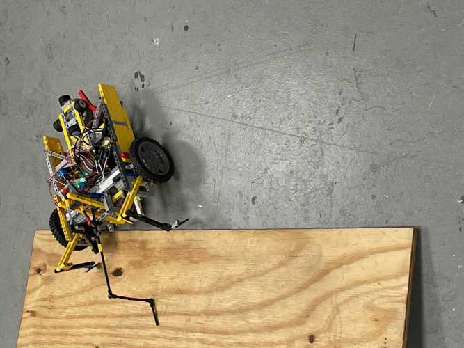 SDC Robot
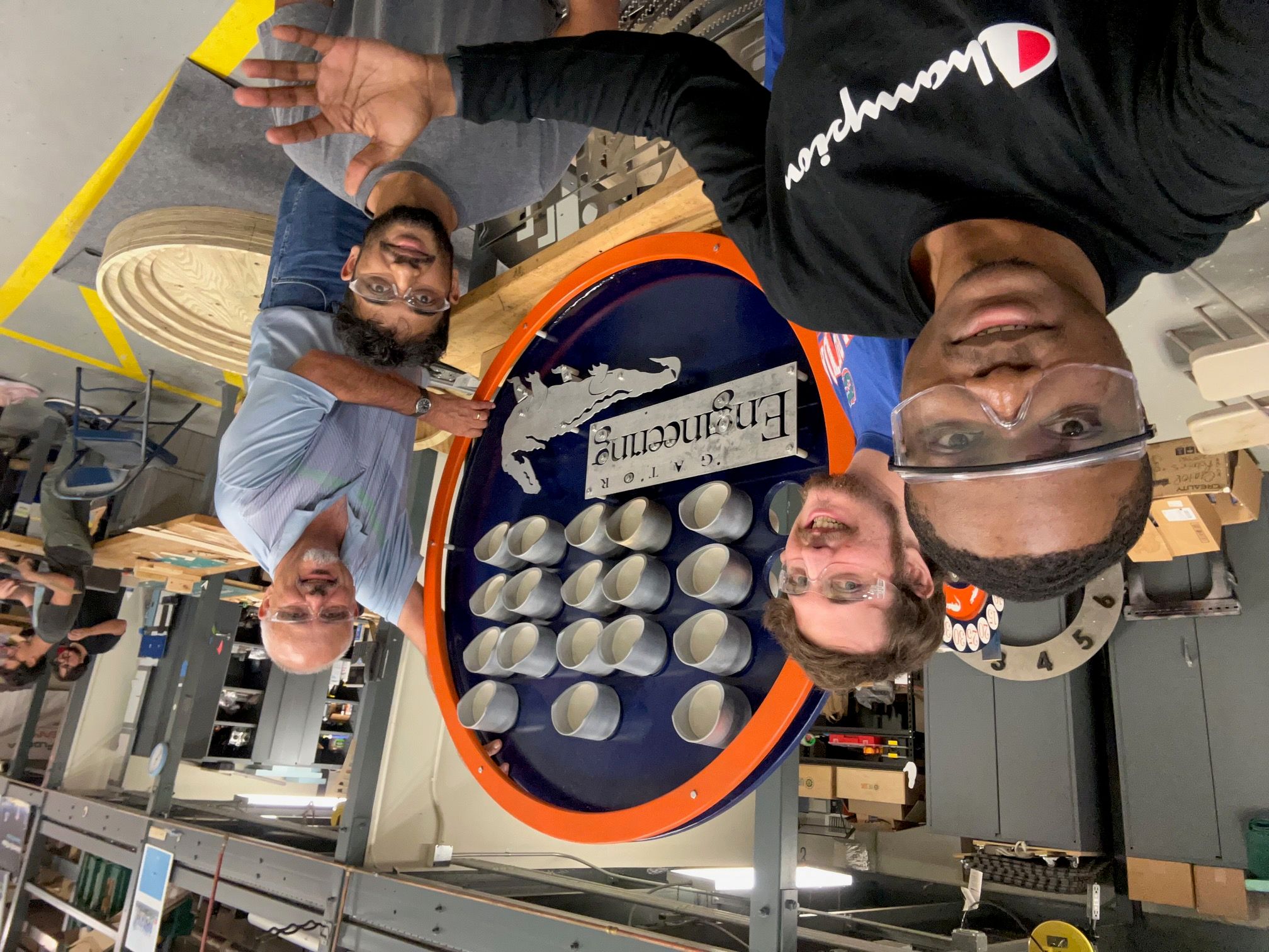 Picture with Dr. Griffis, Monzurul, Emmanuel, and I and the Wandering Dial Clock
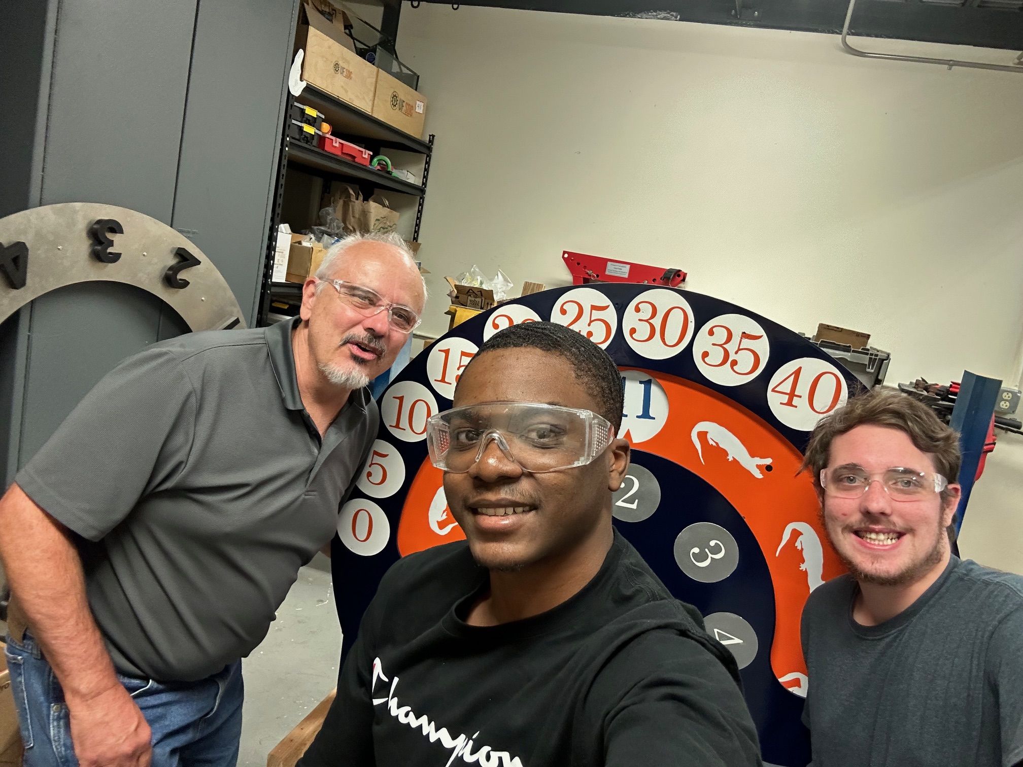 Photo with Dr. Griffis, Emmanuel, and I and the Wandering Dial Clock